


 MENU
MENUProblem:
How do I verify the direction of my unit surface normal vectors to make the correct integrations? If my surface normals point in an inconsistent direction from one timestep to another, how do I correct the value of my integral?
From the User’s Manual:
“Integrations involving surface unit normals, such as Mass Flow Rate, and Forces and Moments integration, rely on surface unit normals pointing in a consistent direction. This is guaranteed for ordered surface zones, but not for finite element surface zones (triangular, quadrilateral, or polygonal), including extracted slices. For these FE zones, the surface unit normal direction for each face is calculated using the right-hand rule with the node order for the face. If the nodes for some faces progress clockwise around the face while other faces’ nodes progress counter-clockwise (as defined by the zone’s connectivity), the faces’ surface normals will point in inconsistent directions, and any integration that relies on these normals will not produce meaningful results.”
Solution:
Surface Normal Calculations and Visualization:
With Tecplot 360’s CFDA variable calculation feature, you can calculate and display surface normal vectors on your plot. This includes the following steps:
1. With the Calculate dialog, calculate the “Grid K Unit Normal (vector)”, using Cell Center as the New Var Location, and “Calculate on Demand” turned off (in case you need to modify the variables as described below).
2. Turn on the Vector layer, selecting the components of the vector you just calculated as the vector components.
3. In the Zone Style dialog, on the Points page, choose “Cell Centers Near Surfaces” as the Points to Plot. For more details on these steps, see the “Surface Normal Calculations” section of the User’s Manual.
You should now see the unit normals displayed. Adjust the vector length, if necessary, using the Vector Details dialog (menu item Plot/Vector/Details). If the normal vectors are not all pointing toward the same side of the surface, contact Tech Support for further assistance.
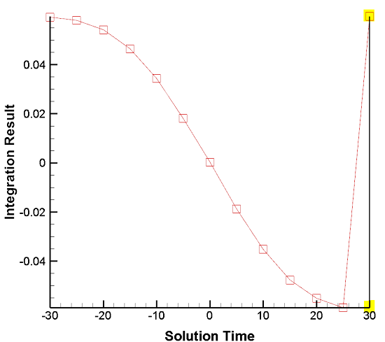
If the normal vectors all point toward the wrong side of the surface (however you define this) in one or multiple zones, you can address this by negating the sign of the vector components¹ of the integrand.² During integration, activating “Plot Result As…” allows you to visually examine integration results per timestep to identify these inconsistencies.
For example: The isosurface of Solution Time 30 (see graph) has surface normal vectors pointing in the wrong direction. We can remedy this by multiplying the vector used in the integrand of the “Vector Dotted with Unit Normal” integral by -1 in the Specify Equations dialog. For example:
{Vel_U} = -1 • {Vel_U}
{Vel_V} = -1 • {Vel_V}
{Vel_W} = -1 • {Vel_W}
For an example of where this information is applicable, see this KB article: Calculating Average Normal Velocity to Iso-Surface
¹ Note: The values of the unit normals utilized in the Integrate feature cannot be manually altered.
² Note: Negating vector components only works for integrations where you specify the vector components. This technique reverses the direction of the affected vectors in that zone. Verify that this is acceptable for your situation. It is not applicable to Mass Flow Rate, and Forces & Moments integrations.